A smart electrical panel replaces or enhances a traditional main load center by integrating digital energy monitoring, automated circuit control, and remote management into your home’s main power hub. While standard panels rely purely on physical thermal-magnetic switches to interrupt excessive current, a smart panel combines those physical overcurrent safeguards with internal current transformers (CTs), electronic relays, and a digital communications gateway. This architecture allows you to track real-time power consumption per circuit, prioritize heavy electrical loads during grid outages, and remotely shed or restore power to specific household branches.
The Safe/Unsafe Verdict
A smart electrical panel is an internet-connected main service panel that provides digital circuit-level monitoring, remote breaker actuation, and automated load management. It is safe to operate as long as physical breakers show no signs of overheating or burning. If you experience unexpected remote breaker trips, immediately isolate the load via the app and verify local physical connections before resetting.
Immediate Safety Status
Before troubleshooting firmware or wireless connectivity issues, confirm that the physical enclosure and electrical bus are safe to approach and handle:
- No Heat Transfer: Touch the dead-front cover with the back of your hand. If the metal panel face is noticeably hot to the touch (above 120°F / 49°C), do not proceed with manual resets.
- No Acoustic Buzzing or Chattering: A faint electronic hum from solid-state relays is normal, but loud arc-like buzzing or rapid contact chattering indicates a failing relay or loose bus connection.
- No Burning Smell or Ozone: Any smell of scorched plastic, hot copper, or ozone requires immediate power isolation.
- Physical Breakers Hold Neutral: Ensure individual breaker handles are fully engaged (ON or OFF) and not stuck in a mid-travel fault state.
- Enclosure Integrity: Verify that no water intrusion, condensation, or physical damage has reached the internal communication board or line-side lugs.
Symptom Branching: Low vs. High Risk
When dealing with smart panel anomalies, separate routine digital communication drops from hazardous electrical hardware failures.
Smart Panel Anomaly Detected
 ├── Telemetry dropouts, app delay, or offline status
 │    └── LOW RISK: Network/Gateway desynchronization (Safe to keep running)
 ├── Automated load-shedding failing to shed during peak demand
 │    └── MODERATE RISK: Logic misconfiguration or firmware timeout (Safe, but requires recalibration)
 └── Rapid relay chattering, thermal discoloration, or uncommanded breaker cycling
      └── HIGH RISK: Physical contact failure or line voltage instability (SHUT DOWN MAIN)
| Symptom / Behavior | Risk Category | Primary Cause | Immediate Action |
|---|---|---|---|
| App shows “Offline” but power flows normally | Low Risk | Wi-Fi gateway disconnect or cloud server delay | Reboot network gateway; check local signal strength. |
| Circuit telemetry reads 0 Watts under load | Low Risk | CT sensor board communications timeout | Perform soft reset on control module via app or panel button. |
| Breaker sheds unexpected load during normal grid operation | Moderate Risk | Overlapping automated logic or incorrect priority rules | Audit automated schedules and load management rules. |
| Loud clicking/chattering from smart breaker module | High Risk | Low control voltage or failing internal relay contacts | Disconnect circuit load; call a licensed electrician. |
| Scorching, melted insulation, or burning smell at panel | High Risk | Loose bus connection or arcing contactor | Shut down main breaker immediately; call emergency service. |
System Analysis (The “Why”)
To understand a smart electrical panel, think of your electrical system as a municipal water network. In a standard setup, water flows through main pipes and branches off through simple mechanical valves (traditional breakers). A smart panel installs an automated meter and an electronically operated valve on every single branch pipe.
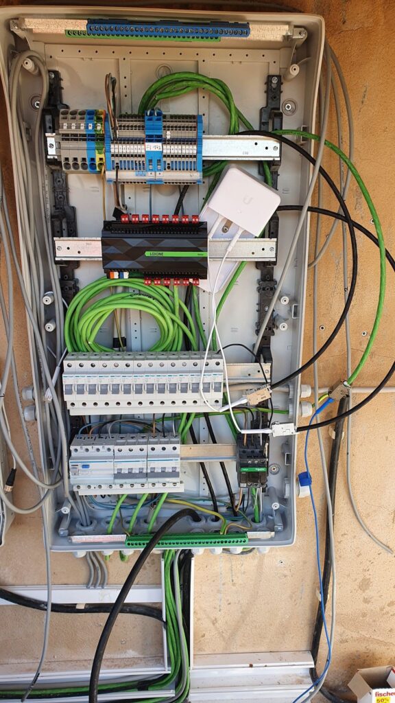
The power flows through a multi-tier chain:
- Utility Utility Mains & Bus Bars: Raw 120/240V utility power enters the main lugs and energizes the heavy copper or aluminum bus bars running down the center of the panel.
- Thermal-Magnetic Trip Engine: Every branch circuit retains a standard mechanical overcurrent element to ensure physical protection against short circuits and code compliance regardless of software status.
- Current Transformer (CT) Array: Integrated CT coils encircle each circuit’s hot conductor, measuring current draw in real time and sending micro-voltage telemetry to the panel’s logic board.
- Solid-State or Electromechanical Relays: Inline electronic switches allow the internal controller to open or close the circuit path based on remote user commands, automated schedules, or power-outage load-shedding rules.
- Telemetry Gateway & Microcontroller: The panel’s brain processes current, voltage, and phase data, then transmits this telemetry to your local Wi-Fi router or cellular gateway.
Because the system relies on both high-voltage power paths and low-voltage digital signal paths, a failure in the digital controller will not strip the panel of its primary safety duty: tripping mechanically during a true short circuit or overcurrent event.
The Most Likely Culprit
When a smart electrical panel behaves unexpectedly, the root cause usually boils down to network or control board failures rather than damaged heavy wiring.
[====================] 60% Wi-Fi Gateway & Firmware Synchronization Faults
[======] 25% Branch Circuit Relay Module Wear or Control Wire Glitches
[===] 10% Microcontroller Hardware or Logic Board Failure
[=] 5% Utility Power Quality / Frequency Instability
- Wi-Fi & Firmware Sync (60%): The vast majority of “failures” stem from dropped local Wi-Fi connections, cloud API latency, or incomplete over-the-air firmware updates that freeze the telemetry processor.
- Relay & Control Wear (25%): Mechanical relays inside smart breakers or smart modules cycle thousands of times over their lifespan. High inductive loads (like air compressors or large air conditioner pumps) can pit contact surfaces or cause control coil chatter.
- Control Board Failure (10%): Voltage surges on the utility line can occasionally damage the low-voltage power supply feeding the internal logic board.
- Utility Power Quality (5%): Voltage sags or abnormal grid frequencies can confuse smart panel logic, causing it to enter protective load-shedding modes prematurely.
The Cost of Delay: 1hr → 24hr
Ignoring early signs of smart panel malfunction can escalate minor digital glitches into costly power interruptions or hardware destruction.
[Hour 1: Minor App Telemetry Offline]
  └── Local panel runs normally; remote monitoring lost.

[Hour 6: Unresolved Relay Chattering]
  └── Internal contactor bounces continuously under load; rapid pitting occurs.

[Hour 12: Thermal Stress on Control Module]
  └── High contact resistance generates localized heat (140°F+); relay welded closed.

[Hour 24+: Systemic Lockout / Panel Component Damage]
  └── Control board short-circuits; physical breaker replacement required ($500+).
Diagnostic Differentiators
Homeowners often confuse full smart electrical panels with add-on monitoring hardware or individual smart plugs. Here is how they differ fundamentally in architecture and control capability:
| Feature / System | Integrated Smart Panel | Standard Panel + CT Energy Monitor | Smart Breaker Retrofit Modules |
|---|---|---|---|
| Circuit Monitoring | Per-circuit integrated CTs | Clamp-on CTs on select circuits | Integrated into individual smart breakers |
| Remote Actuation | Full remote control (ON/OFF/Shed) | Read-only (No load switching) | Remote control on equipped circuits |
| Load Management | Automated, dynamic outage shedding | Manual intervention required | Basic scheduled shedding |
| Installation Scope | Full panel replacement or subpanel | Easy add-on into existing panel | Breaker swap out in compatible panels |
| System Complexity | High (Requires complete rewiring) | Low to Moderate | Moderate |
The “Right Now” Protocol
If your smart panel displays erratic behavior, follow this non-invasive diagnostic protocol immediately:
- Verify Physical Power: Walk to the panel and check if essential home loads are receiving power despite app discrepancies. If power is normal, the issue is strictly isolated to the telemetry network.
- Perform a Controller Soft Reset: Locate the panel’s low-voltage reset button (typically found behind the dead-front door or on the gateway module). Press and hold for 5–10 seconds to reboot the communication bus without interrupting power to the house.
- Inspect App Override Settings: Open the management app and check if an automated “Load Shedding,” “Time-of-Use,” or “Grid Outage” profile is actively forcing branch circuits off.
- Isolate High-Draw Loads: If a specific smart breaker is chattering or dropping offline, manually flip that individual breaker to OFF to prevent relay coil damage until a technician arrives.
- Check Router Connection: Reboot your local internet router to clear dropped IP leases on the panel’s Wi-Fi module.
Red Flag Stop Triggers
WARNING: CRITICAL HARD-STOP CONDITIONS
Cease all manual troubleshooting and isolate power at the main service disconnect if you observe any of the following symptoms:
- Visible smoke, melting plastic, or charring around smart breaker modules or line lugs.
- Loud, continuous arc-like buzzing coming from the interior bus structure.
- Thermal readings above 140°F (60°C) on breaker casings using an infrared thermometer.
- Repeated tripping of the Main Service Breaker (indicates a severe bus fault or phase-to-phase short).
- Water entering the enclosure through conduit feeds or panel seals.
The Professional Inspection Path
When a field technician arrives to evaluate a malfunctioning smart electrical panel, they perform a structured set of tests using specialized tools:
[1. Thermal Imaging Scan] ──► [2. Voltage & Phase Check] ──► [3. Gateway Bus Test] ──► [4. Insulation Meggering]
- Infrared Thermal Scan: The technician uses a FLIR thermal camera to scan bus connections, breaker terminals, and internal relay bodies under full load to identify high-resistance hot spots.
- Line Voltage & Phase Balance Verification: Using a digital multimeter (DMM), the technician measures phase-to-phase (240V) and phase-to-neutral (120V) levels at the main lugs to rule out utility supply imbalances.
- Communication Bus & Signal Diagnostics: The electrician tests the low-voltage RS-485 or CAN bus data lines linking the smart breakers to the central gateway to ensure proper voltage levels and data packet transmission.
- Relay Contact Resistance Test: The technician measures voltage drop across closed smart relay contacts under load to confirm the internal contacts haven’t pitted or degraded.
- Insulation Resistance (Megger) Testing: If a branch circuit continuously triggers protective shutoffs, a megohmmeter applies 500V DC to verify conductor insulation integrity.
Estimated Repair & Replacement Cost
Costs vary based on whether the issue is limited to communication modules or requires physical panel replacement.
| Severity Level | Work Required | Typical Parts Cost | Estimated Labor | Total Expected Cost |
|---|---|---|---|---|
| Minor | Gateway module reboot, firmware flash, or antenna extension | $0 – $100 | $100 – $200 | $100 – $300 |
| Moderate | Single smart breaker or relay module replacement | $150 – $350 | $150 – $300 | $300 – $650 |
| Major | Main control board replacement or bus wiring repair | $400 – $900 | $300 – $600 | $700 – $1,500 |
| Systemic | Full smart electrical panel replacement (Panel + Breakers + Labor) | $2,000 – $4,500 | $1,500 – $3,000 | $3,500 – $7,500+ |
Symptom Escalators
If your smart panel troubleshooting reveals deeper logic errors, telemetry faults, or load management issues, refer to these specific diagnostic guides within our knowledge base:
- If you need to understand how the internal logic board coordinates power between grid, solar, and battery storage, see System Logic: How Smart Breaker Panels Work.
- If you want to evaluate CT-clamp monitoring options without breaker control, review Monitoring Logic: Smart Panels vs. Home Energy Monitors.
- If your smart panel is failing to shed heavy loads during grid power outages, consult Active Control: Smart Panel Load Management Features.
Final Circuit Check
Smart electrical panels represent a significant step forward in residential power distribution, giving you visibility and control over individual household circuits that traditional panels simply cannot match. However, because they combine high-voltage distribution with low-voltage electronic relays and network gateways, erratic behavior is far more likely to stem from network connectivity or logic settings than from hardware failure. If your panel’s physical breakers hold steady and show no signs of excess heat or noise, take a systematic approach: reboot the communication gateway, check your app automation profiles, and let the system re-establish its digital handshake. If thermal elevation, mechanical chattering, or odor occurs, isolate power at once and let a qualified electrician handle the diagnostic path.